Radar Rendering the invisible visible
Engineers from Bochum and Duisburg-Essen are developing a technology that is partly only known from films.
It sounds like science fiction, the plan devised by researchers involved in the new collaborative research centre named “Marie”: they want to create a flying platform capable of generating a three-dimensional representation of its surroundings. Film enthusiasts might recognise the technology from the movie “Prometheus”, where robotic spheres dart through cave tunnels, scan their surroundings autonomously, and transmit the data in real time to a spacecraft where they are rendered visible in a 3D map.
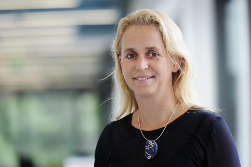
In the real world, the devices shall be based on a combination of radar and laser. The technique could be, for example, deployed in order to find out what firefighters might encounter behind clouds of smoke in a burning building. The system is supposed to not only detect where something is in a room, but also to determine its properties – if it is a burning box or a person lying on the ground, for example. “This is our vision,” Prof Dr Ilona Rolfes from Ruhr-Universität Bochum says, who is co-spokesperson at the collaborative research centre transregio (SFB/TRR) 196. “But we still have a long way to go.”
One process, two applications
In order to succeed, a number of high-frequency technology fields have to be brought together: material characterisation, radar imaging and radiolocalisation. This is the objective pursued by the team of the collaborative research centre “Marie”, short for “Mobile Material Characterisation and Localisation by Electromagnetic Sensing”, which was founded in 2017. For this purpose, the engineers from Bochum are collaborating with researchers from the University of Duisburg-Essen headed by SFB spokesperson Prof Dr Thomas Kaiser.
This is how the technique works
In principal, the same measurement technique should be suitable for material characterisation as well as localisation. However, it is not yet being used simultaneously for both. The measurement principle is as follows: a radar emits electromagnetic waves that are reflected by objects. A receiver records the returning waves. But the signal transmitted by the radar source does not remain constant throughout. Rather, the frequency of the transmitted waves increases continuously over a certain period of time, for example from 200 to 250 gigahertz in a few milliseconds.
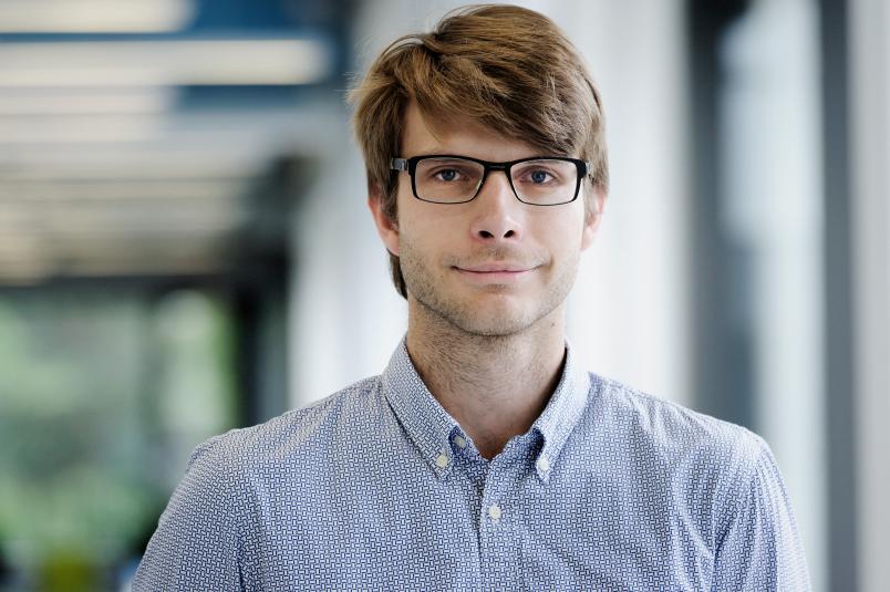
Dr Jan Barowski from the Institute of Microwave Systems in Bochum explains: “The received signal that was reflected by the test object has a specific delay with respect to the transmitted signal. That means it takes a while before the first waves hit an object with 200 gigahertz and are reflected by it.”

By the time the 200 gigahertz signal is reflected by the object and arrives at the receiver again, the frequency at the source has risen by ten kilohertz, for example. This is because the transmitted frequency at the source increases continuously. The further away an object, the longer it takes for the waves to reach the object and to return to the receiver. The larger the delay is, the greater is the difference between the frequency of the reflected signal and the signal that is now being transmitted by the source. Consequently, researchers are able to calculate the distance between object and source based on the frequency difference.
Material characterisation using radar
Additionally, the returning waves provide even more information. The strength of the reflected signal is determined by the size of the object, by its shape and by its material properties. This is because certain materials reflect more strongly than others. Air, for example, is a material through which electromagnetic waves pass uninhibited. Materials with many air pockets, such as polystyrene, reflect hardly any radiation at all, whereas metal reflects very strongly.
A material parameter, the so-called relative permittivity, describes the electromagnetic material properties; it also depends on the frequency of the transmitted signal. Consequently, researchers can calculate the relative permittivity based on the strength of the reflected signals. The evaluation of the frequency dependent behaviour, indicates what kind of material the object is made of.
Eliminating measurement errors
In the beginning the technology must be optimised. “The challenge is that an ideal measurement system does not exist. Errors occur in all measurements and we have to correct them,” Jan Barowski says . An example of one of the many potential sources of error is as follows: the power of a signal dwindles away en route between the radar set and the object – this must be taken into consideration when performing the analysis. In his PhD thesis, Barowski developed algorithms to compensate for these signal losses and to systematically correct errors arising in internal sources of the measuring system.
By the end of the process, the “Marie” method is supposed to generate an image of the room that includes information about the distribution of materials. The researchers must therefore combine material characterisation with radar imaging. Barowski elaborates the challenge they’re facing: “To date, material characterisation has been performed only in defined spots, pretty much like pricking an object with a needle.”

The data we record can be compared to those of a camera that lacks a lens for focusing.
Jan Barowski
Converting a radar signal into an informative image requires huge computational cost. “The data we record can be compared to those of a camera that lacks a lens for focusing,” Barowski explains. In the raw data, point targets appear as hyperbolas or circles. Focusing is taken care of in the next step by postprocessing the signals. For this purpose, the engineer has likewise created algorithms that remove errors from the images in real time.


“When I first started out, such corrections used to take us ten hours,” he remembers. Today, the analysis is performed in real time via a laptop graphics card. “The computer architecture of a graphics card is perfect for our purpose,” Barowski points out.
Looking through drywall
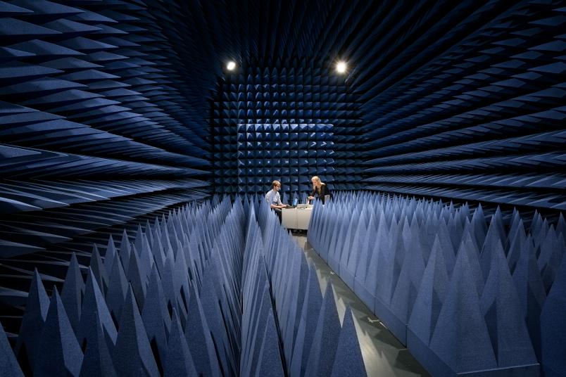
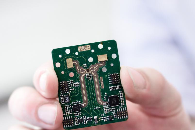
In the RUB lab, it is already possible to view this technology in action, namely by using radar to look through a drywall sheet. Two radar devices are mounted on a movable rail. One measures the position of the system relative to a fixed point in the room; the other scans the surface below the drywall sheet, rendering visible the concealed objects. As the radars move along the drywall sheet, an image of the objects below is displayed on a laptop monitor. The algorithms used to process the signals as well as the radar devices have been developed in-house. The hardware of the radar systems is studied for the “Marie” project by Prof Dr Nils Pohl and Prof Dr Thomas Musch at RUB, in close collaboration with Dr Werner Prost from the University of Duisburg-Essen, to name but a few.
Jan Barowski’s conclusion so far: “Using our system as it is today, we are able to determine the position of an object – and ascertain that it must be made from a different material than, for example, the surface on which it lies,” he says. “In the next step, we will attempt to identify what kind of object we are dealing with.” The engineers are already capable of identifying the permittivity of synthetic materials. “However, we cannot exactly specify the synthetic material in question as yet, because some of the values are close together,” the researcher continues.
Step by step towards reality
Now, the SFB team intends to move away from the ideal system in the lab and to approach reality, where the radar system would neither know the distance to the test object in advance, nor be aware from which angle it is viewing the object. The aim is, after all, to create a mobile platform by the end of the project.
Such a flying system could calculate its own position in the room to the millimetre, for example via RFID (radio-frequency identification) that facilitates contactless determination of the position using electromagnetic waves. Project partners from Duisburg-Essen are already working on the technology, in collaboration with the Fraunhofer Institute for Microelectronic Circuits and Systems in Duisburg and Technische Universität Darmstadt.
Higher frequencies
In cooperation with Prof Dr Ulrich Pfeiffer from the University of Wuppertal, electronic signal sources are being researched that are capable of generating exceptionally high frequencies; the team plans to experiment with frequencies up to 1.5 terahertz during the first phase of the SFB/TRR. At the same time as electronic sources, photonic – i.e. laser-based – measurement systems are also being developed: in Bochum by Prof Dr Martin Hofmann and Dr Carsten Brenner, in Duisburg by Prof Dr Andreas Stöhr. The long-term purpose of the different approaches – electronic and photonic – is to enhance the frequency range in subsequent project phases to up to four terahertz, since different frequencies provide different information about the analysed objects.

In Duisburg, the team headed by Thomas Kaiser is building a test lab where the measuring system can be moved through the room on huge robotic arms. “We’ll be able to set up different scenarios and generate specific interferences, in order to test our systems under realistic conditions,” Ilona Rolfes explains. A fire lab where smoke and flames can be created already exists in the facilities run by the project partners Prof Dr Ingolf Willms and Dr Thorsten Schultze.


