Civil engineering
Bridge construction with spoilers
For bridges under construction, as little as a fresh to strong wind can be fatal. Potential safety devices are tested in wind tunnels.
Motorway bridges, no matter how long, are often passed quickly at speeds of over 100 kilometres per hour. On closer inspection they are all the more impressive: sometimes several hundred metres long, they bridge valleys or rivers at dizzying heights. But how are they built?
“Today, such bridge superstructures are usually built using the incremental launching method,” says Professor Rüdiger Höffer, head of the Wind Engineering and Fluid Mechanics working group at the Institute for Structural Engineering at the RUB Department of Civil and Environmental Engineering. “This technique is fundamentally different from building a bridge superstructure on falsework or using the cantilever method. Today, the whole process is more mechanised. For bridges, first an abutment and the subsequent supports are built. At the finished abutment – the place where the bridge is to begin – a field factory is set up simultaneously, which manufactures the sections of the bridge on site in a series production or where prefabricated segments are inserted. These are then advanced bit by bit from the abutment under the high pressure of several presses in the direction of the supports that have been built in the meantime, while new parts are constantly added to the abutment. This is how the bridge initially grows into the void but then reaches the supports and is pushed onto them – experts refer to this as incremental launch.
120 metres into the void
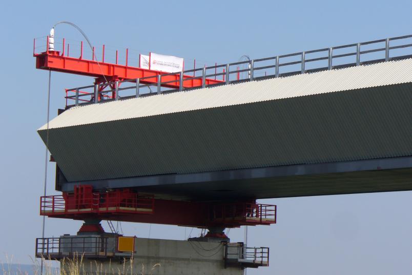
The dimensions are huge: whereas in the 1980s only bridges up to about 40 metres in total span were built in this manner, today the distance between two supporting pillars can be more than 120 metres. The superstructure of the bridge during the incremental launching process is made as a steel box open at the top. “You can picture it in cross-section like a wide U,” as Höffer illustrates. The stabilising concrete deck will be added later, because it would be much too heavy for this construction technique. A single such section can be 15 to 30 metres long. It is pushed towards the next support at a rate of a few metres per hour, then the next one is mounted and screwed to it. “If everything goes well, you can bridge the distance between two supports – we refer to it as a field – within a few days,” explains Rüdiger Höffer.
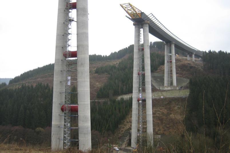
Because gravity pulls the top of the launched bridge downwards, a so-called launching nose is attached there, a kind of lattice girder that has a triangular shape and slides onto the next support to lift the bridge onto it. This nose can be a good 30 metres long, in some cases 40 metres.
This huge size sheds light on the forces acting on the individual parts. In addition to the high compressive and tensile stresses that act due to the dead weight in the various cross-sections of the components, loads of the assembly material and from assembly work likewise affect the growing bridge. Far more critical, however, can be the effects of the wind.
The dreaded wind gusts
“The open-top U of the superstructure with its mostly inclined walls is very vulnerable to wind,” explains Höffer. The steel structure bends or twists. The wind can deform it in three directions. The most dreaded are gusts of wind are those that cause the emerging bridge to vibrate: one gust of wind that causes a vibration is followed by another that amplifies the vibrations: the structure starts to swing. “A storm or a thunderstorm can lead to amplitudes in the metre range,” points out Rüdiger Höffer. But even smaller vibrations can damage the structure, because the vibrations put cyclical stress on the clamping point of the bridge at the abutment or above the already passed support. These areas of the structure are actually designed to withstand millions of light vibrations. During a storm in the construction phase, however, merely a few hundred stronger rocking motions are enough to cause micro-cracks that necessitate costly renovation or even replacement of structural parts. This is why engineering teams want to avoid such vibrations at all costs.
One way of preventing wind uplift can be to attach a counter-vibrating mass to the launching nose, a so-called vibration damper. The mass of such a system can be a ton or more. It vibrates in counter-cycle to the vibrations of the bridge girder. As a result, it can reduce the amplitudes of the structural vibration, but it is very complex and expensive to construct and adjust. Moreover, it only works in one degree of freedom, i.e. in one direction of vibration. Wind-induced vibrations, however, such as can occur on bridge superstructures while they’re being launched, are often three-dimensional. Therefore, it is more effective to avoid vibrational excitation by controlling the wind forces.
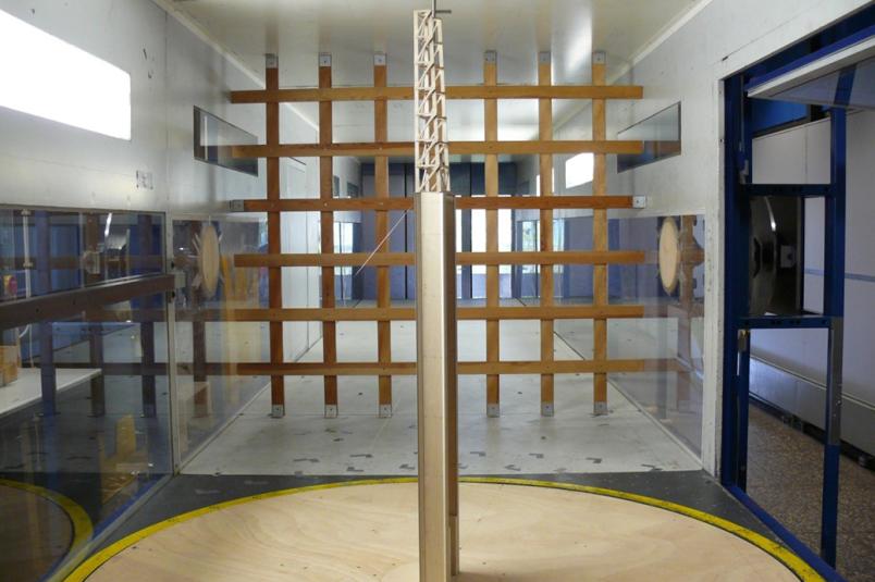
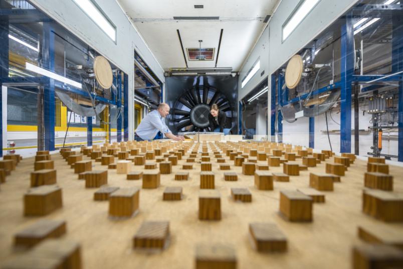
The wind engineers at RUB, headed from 1970 to 2000 by Höffer’s predecessor, Professor Hans-Jürgen Niemann, and subsequently by Höffer himself, have been studying such wind-excited vibration phenomena at RUB for 50 years. New construction methods invariably entail new problems. “Some phenomena, which are originally known from aircraft construction, often occur in buildings today due to the new construction techniques and methods,” explains Höffer. One example is the viaduct of the A46 motorway near Nuttlar, built about ten years ago. The tallest support is 115 metres high, the largest distance between two supports is also 115 metres. During the examination of the construction drawings of the bridge on behalf of Straßen.NRW, the problem of possible wind-induced vibrations came to light. Straßen.NRW commissioned a study in the boundary-layer wind tunnel at RUB, which is operated by Rüdiger Höffer’s research group. “By then, the construction site was already set up,” says Höffer.
Closing the U
Although the issue had been discovered at this late stage, it was possible to find a solution to the wind problem and advise the road construction authority accordingly: “In cooperation with our spin-off, the engineering firm Niemann Ingenieure that is based in the Technology Centre next to the campus, we carried out specific wind tunnel experiments and jointly suggested closing the U of the still unfinished bridge at the top with metal sheets or wooden panels to prevent the wind from getting in,” explains Rüdiger Höffer. With this special cross-section and taking into account the vibration properties of the feed cross-section at the crucial incremental launching positions, this was enough to defuse the danger posed by the wind. This method set a precedent and has been further developed. Since then, the transverse steel girders that later support the concrete deck of several other bridges have been covered with sailcloth to control the wind flow field.
“Streamlining the awkward shapes of the bridge under construction is the most elegant way to cheat the wind,” says Rüdiger Höffer. In addition to closing the U, the team at the engineering firm Niemann Ingenieure and the boundary-layer wind tunnel research unit also develop appropriate spoilers, or more precisely: air-guide linings. They can take many forms: laterally attached wind deflectors in the shape of an acute triangle reduce vortex shedding that cause vibrational excitation.
Unstiffened supports of the bridge still under construction are also at risk from the wind, especially in tall structures. Special attachments, for example made of wooden panels, can break up dangerous periodic vortex shedding. However, since they also increase the wind resistance of the support, it must be strengthened from the outset with stronger reinforcement made of steel in the concrete. It is therefore necessary to know before building the support whether the add-on parts have an aerodynamic necessity and, if so, to dimension the support for the somewhat higher wind resistance. A structural aerodynamic boundary-layer wind tunnel, such as the Bochum wind tunnel, is required for a safe preliminary analysis.
Shock absorber on the rope
In suspension bridges, the cables are a point of attack for the wind, and this must be taken into account. “In Japan, a bridge was built in the 1990s whose cables had a smooth coating to protect them from dirt and ageing,” says Rüdiger Höffer. When it rains – and it often rains in Japan – small rivulets form on it. If a light wind causes these rivulets to move fore and back on the surface of the rope, it is enough to make the rope swing dangerously because of its minimal damping. Therefore, vibration dampers are installed at the base of the rope to increase damping to a sufficient extent.
From cooling towers, to stadiums, bridges and wind turbines
Höffer stresses that new studies are needed for every new construction project. Since 2004, his team has also specialised in the numerical simulation of the effects of wind on buildings. They are used, among other things, when construction plans are still being adjusted after the actual analysis in the wind tunnel or when small-scale details are to be examined that are difficult to measure in the wind tunnel.
“For a long time, the wind tunnel at RUB was the world’s number one for testing projected cooling towers,” Rüdiger Höffer recalls. “Following the German energy revolution, they are no longer built as often today, at least in Europe.” But the engineers are not running out of work: in addition to stadiums and bridges, they now also analyse the support structures of wind turbines in the wind tunnel.
